Ambilight Tutorial
Works With Any HDMI Source
(Responsive TV Backlighting)
Author: Chris Majestic
Last Updated: May 26, 2021
Let’s Make This Easy
I originally wrote this tutorial back in May of 2020 and a lot has changed since then. I’ve spent several days rewriting this tutorial to make it easier to follow and update some of the methods. I’m not a micro electronics expert. I just did a bunch of research on this project and wanted to compile it all into one place for people to find it. I’m going to try to make this tutorial as detailed as possible and explain it in a way that anyone can understand. I will be updating this tutorial as things change and I find better ways to do this.
Sections
What is Ambilight? Is It Beneficial?
Before I get into the tutorial I want to talk a little bit about what Ambilight is and how it works. The name “Ambilight” was taken from the Philips Ambilight TVs. These TVs have LEDs built into the back of the panel that light up different colors that match the colors of the video that is playing on the screen. This adds a novelty lighting effect on the wall behind the TV depending on what content is being displayed on your screen.
Ambilight is sometimes called Bias Lighting and although they are similar, bias lighting is slightly different. Bias lighting is usually white, subtle, and reduces eye strain by improving perceived contrast. This is easier on your eyes since viewing a bright screen in a dark room can cause eye fatigue which can lead to headaches, discomfort, and other side effects.
Ambilight may not be popular with home theater purists who only want to see a movie or show as it was intended, but for the rest of us who like cool lighting effects, this is a great way to change your video experience.

How Can We Do This?
So how do we accomplish this? Well there are a few ways to do this but in this tutorial we’ll use a Raspberry Pi, Individually Addressable LED light strips, and an HDMI capture device. With this setup you can capture video from any HDMI device such as a game console, Blu-ray player, or media streamer and LEDs mounted on the back of your screen will mimic the video on your screen.
You might notice that some tutorials don’t include an HDMI capture device. Those tutorials assume that you will be playing content directly from a Raspberry Pi, Android device, or computer.
The method we will be using in this tutorial still allows you to link with certain devices such as a computer or Android device, but it will not work for the apps built into your TV. In other words, if you have a Roku TV this method will not work with your Roku apps. You will have to use an external streaming device such as a game console, Apple TV, Chromecast, or external Roku streamer.
Difficulty level for this project: 7/10
If you’re not comfortable dealing with electrical components and circuitry then this project may be intimidating. It’s not difficult as long as you take the necessary precautions. Most of the components in this project are low voltage but if you need a large power supply you may be required to work directly with live AC voltage. Working with AC voltage can be very dangerous and even fatal. If you don’t feel comfortable with this then you can use a sealed power supply or consult with a licensed electrician.
Alternatives To The DIY Method
Pre-packaged Ambilight Kits

There are a few alternatives to the DIY method. The first alternative is to buy a pre-packaged Ambilight kit. Some of these kits, such as the Philips Hue HDMI Sync box, work very similar to what we will be building in this tutorial. If you don’t have a very large TV this may be a viable option.
Other kits connect to your TV via USB and attempt to capture your screen internally and some even use a camera to capture the screen. The downside to these kits is that they often don’t work as as expected and they don’t usually fit very large screens. So if you’re like me and have a 135” projector screen these kits won’t work.
Philips Hue HDMI Sync Box
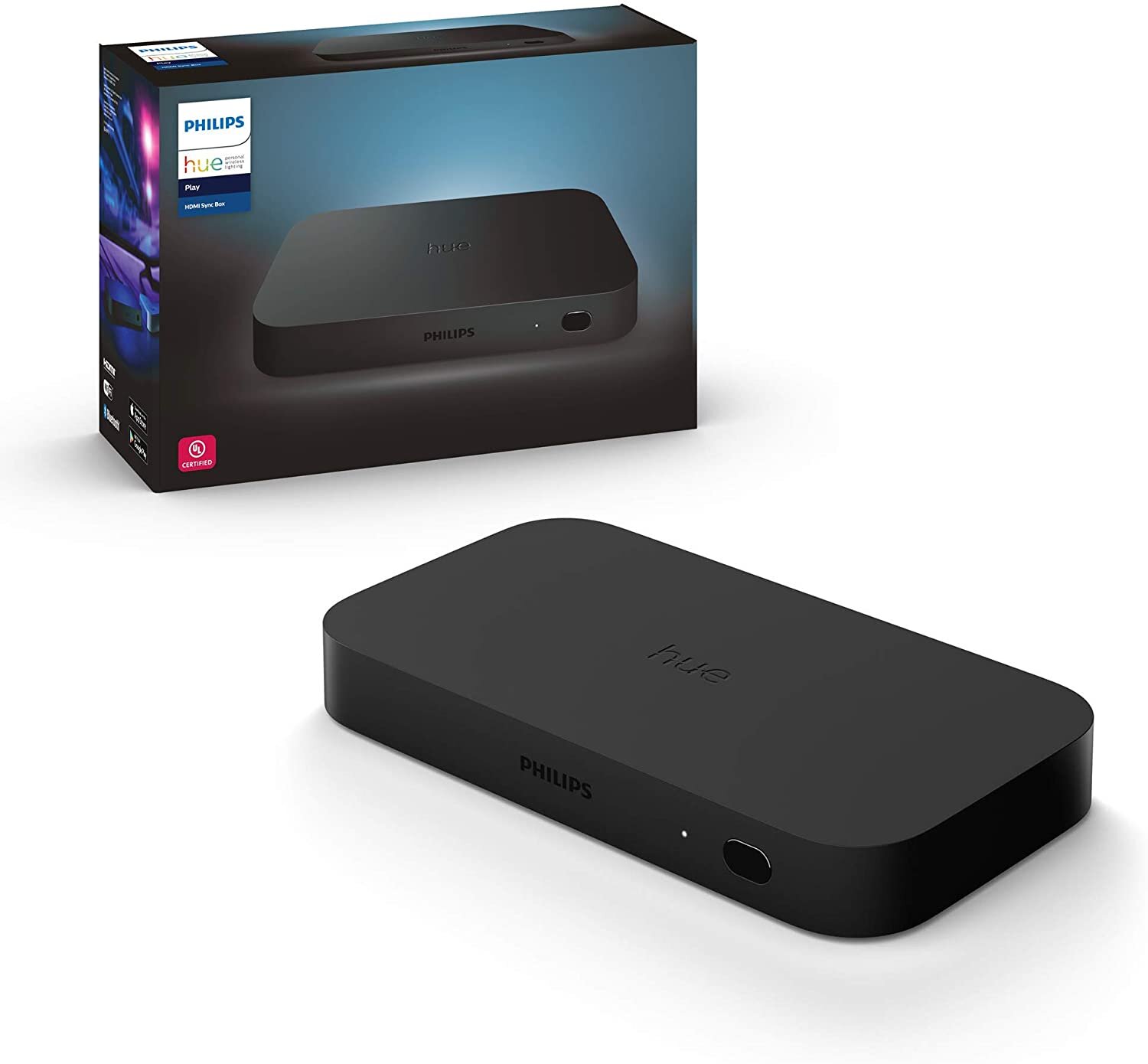
Philips Hue HDMI Sync Box
A popular alternative is the Philips Hue HDMI Sync Box with Philips Hue Lightstrips. This is probably the easiest option but it’s also the most expensive.
Update: Philips Hue recently released the Philips Hue Gradient Light Strips which allows each LED in the strip to addressed individually for a more dramatic effect compared to their basic light strips. With the Original Hue Lighstrips the effect was much less dramatic since the entire strip could only produce one color at a time.
There are two downsides to the Philips Hue setup. The biggest issue is cost.
Philips Hue HDMI Sync Box = $230
Philips Hue Play Gradient Lightstrips
55 inch version = $200
65 inch version = $220
75 inch version = $240
That’s a total of $430 if you have a 55 inch TV.
Philips Hue Gradient Lightstrips
The cost of the Ambilight setup we’ll be building in this tutorial ranges from $150 to $300 and will look better, have better compatibility with other sources, and will work for ANY size screen. Aside from cost, the other issue with Philips Hue is that the Gradient Lightstrips don’t support TVs over 75” since they’re not long enough. The Hue strips also don’t light up the bottom of the screen which might be a turn off for some people.
On the other hand, the Philips Hue option is very easy to setup and it allows you to easily sync with other Hue lights in your room. So if you have Philips Hue bulbs around your room they can also respond to the colors on the screen. This gives you have the ability to light up your entire room with the content on your screen which is pretty cool. The method we’ll be using in this tutorial will allow you to sync with Philips Hue lights as well.
If you find that this tutorial is too overwhelming then Philips Hue is a great alternative.
What Parts Do I Need To Get Started?
Aside from an internet-connected computer and a network connection for the Raspberry Pi, you will need several parts. Listed below is a list of required and optional parts with a brief description of each item as well as some alternatives. Please read the product list descriptions below to determine exactly which product you should buy for your desired setup.
Required Parts
(Amazon Affiliate Links)
1. Raspberry Pi – Amazon Link
The Raspberry Pi will be used to run the Hyperion server, process the video from the HDMI grabber, and control the LED strip. This guide previously required an Arduino board but it is no longer required. You could technically go with any Raspberry Pi but I recommend the Pi 3 or Pi 4 since they are powerful enough that you shouldn’t have any processing issues. I personally went with the Pi4 but the downside is that it runs pretty hot. If you choose to go with the Pi4 be sure to at least install some heat sinks. If you’re really worried about heat then the Pi3 runs cooler.
2. WS2812B LED strip – Amazon Link
The WS2812B is an Individually Addressable (IC) LED strip. In other words, each LED on the strip can be controlled independently which allows the Raspberry Pi to send specific color and brightness parameters to each LED. Be mindful that these LEDs come in 3 different variants. 144 LEDs per meter, 60 per meter, and 30 per meter. I’ve found that 60 per meter provides the best effect. The strips usually come in lengths of 1 meter or 5 meters and can be easily cut so it’s better to buy more than you need and trim them down to the length you need. To cover a screen larger than 80 inches you will need more than one strip unless you’re okay with a gap at the bottom of your screen. They also come with different types of waterproofing: IP30 (no protective covering), IP65 (silicone resistance), and IP67 (silicone sleeve waterproofing). I recommend IP30 to most people since they are the most flexible and water resistance is not required in most applications.
3. 5 Volt Power Supply – Amazon Link
Unfortunately, the Raspberry Pi doesn’t provide enough power to drive the WS2812B LEDs so you will need a 5 volt (5V) power supply. The required power supply amperage depends on your setup and the number of LEDs you have. Each LED can draw a maximum of about 60ma. As a general guideline I would recommend at least a 10 amp (10A) power supply.

It’s important to note that if you plan on running more than 300 LEDs you will probably need a large metal power supply. These type of power supplies have exposed high voltage AC contacts which can be very dangerous if you’re not careful. If you purchase one of these power supplies I highly recommend putting it inside of a project box for better safety. Alternatively you could use a smaller power supply but just keep in mind that the LEDs may not go to their full brightness. Please see the “Wiring The LED Strip” section of this guide for more info.
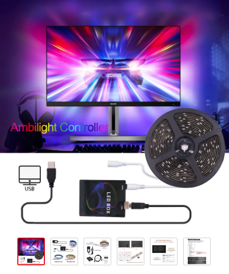
4. HDMI to USB Capture with Loop Out (Grabber/Splitter) - Amazon Link
This HDMI to USB Capture Device connects to a USB port on the Raspberry Pi and is used to capture the video from your media player so the Pi can process it. This capture device also has a “Loop Out” which allows you output up to 4K (non-HDR) video to your TV since it has an HDMI output which is helpful since this project requires you to send video to both your TV and a Raspberry Pi. . If you don’t care about 4K HDR this eliminates the need to buy a separate HDMI splitter. If you do plan on watching 4K HDR content then you will need to choose one of the other options below.
It is important to note that most HDMI to USB capture devices suffer from a small amount of latency/lag which can cause the LEDs to have a slight delay which can be distracting. There are ways to slightly lower the latency in the Hyperion settings but if you want the least amount of latency then you could use the HDMI2AV converter and Composite USB Grabber as an alternative. There are drawbacks to that option as well but the major benefit to using the HDMI to USB Capture Device is that it provides a digital video signal which allows the LEDs to respond more accurately compared to the HDMI2AV option. (See the “Optional Parts” section below for more info).
5. 4K HDR HDMI Splitter – Amazon Link
Although the HDMI to USB capture With Loop Out (mentioned above) usually works fine if your TV is 1080p, it will not work for a 4K TV. Additionally, splitting a 4K HDMI signal is fairly complex thanks to HDCP (High-Bandwidth Digital Content Protection) and it’s usually one of the reasons that people give up on this project. If you have a 1080p TV/Projector then this shouldn’t be an issue. However, if you plan on watching 4K HDR content on a 4K TV then you’ll likely run into issues with an cheap splitter. I’ve found two HDMI splitters that work well for 4K content. The one I recommend to most people is the gofanco Prophecy 1x4 2.0 Gaming HDMI splitter.
Aside from HDCP issues, another issue that often comes with splitting a 4K HDR signal is that the video going to the 2nd HDMI output (your Raspberry Pi) will lack vibrant color and appear “washed out”. Although it’s not cheap, this splitter is one of the cheapest options I’ve found that fixes this issue since it has SDR tone mapping. This makes your LEDs match the colors on your TV when you watch 4K HDR video. The only alternative I’m aware of is the HDFury Diva which is a high-end HDMI splitter listed in the “Optional Parts” section below. See further down in the tutorial for more detailed information on this.
6. HDMI to USB Capture (Grabber) - Amazon Link
This HDMI to USB Capture Device is basically the same as the HDMI to USB with Loop Out that is listed above but it doesn’t have an HDMI output. If you plan on using a 4K HDMI splitter then you’ll want to buy one of these since we don’t need the loop out function.
The HDMI to USB capture device (grabber) connects to a USB port on the Raspberry Pi and is used to capture the HDMI video so the Pi can process it. Again, it is important to note that most HDMI to USB capture devices suffer from a small amount of latency/lag which can cause a slight delay in the reaction of the LEDs which can be distracting. There are ways to slightly lower the latency in the Hyperion settings but if you want the least amount of latency then you could use the HDMI2AV converter and Composite USB Grabber as an alternative. There are drawbacks to this but the major benefit to using this HDMI to USB Capture Device is that it provides a clean digital video signal which allows the LEDs to respond more accurately compared to the HDMI2AV option. (See the “Optional Parts” section below for more info).
7. USB Power Adapter For Raspberry Pi - Amazon Link
You can power the Raspberry Pi with any 5 volt power supply using the GPIO pins. However, the safest way to power the Pi is to use a separate USB power adapter. This is the official 3 amp USB Type-C power adapter for the Raspberry Pi 4. If you’re using an older Raspberry Pi such as the Pi2 or Pi3 then you will need a Micro USB power adapter.
8. Jumper Wires – Amazon Link
These wires will be used to connect to the GPIO pins on the Raspberry Pi. This includes connecting the Raspberry Pi to ground, connecting a logic level converter if you need one, and connecting the LED data wire to the Raspberry Pi. They should not be used for any high voltage applications.
9. 16-Gauge Electrical Wire – Amazon Link
These wires will be used for all electrical connections that require longer wire than the jumper wires. This includes powering your LED strips and connecting the data wire from the Raspberry Pi to the LED strip.
10. 32GB Micro SD Card – Amazon Link
The micro SD card will be used as the primary storage device for your Raspberry Pi. Any Class 10 (or faster) SD card can be used. I recommend at least a 4GB SD card.
11. SD Card Reader - Amazon Link
The SD card reader will be used to write to the SD card from your computer. We will use this to install the Raspbian OS on the SD card. If your computer has an SD card reader then this part is not necessary.
Optional Parts:
1. Logic Level Converter - Amazon Link
If your Raspberry Pi will be positioned farther than 5 or 6 feet away from your LED strip then you may need to use a Logic Level Converter. The logic level converter converts the 3.3v signal from the Raspberry Pi to a 5v signal and allows you to send the data over a much longer distance. If you notice strange behavior from the LEDs such as sporadic flashing or flickering every few seconds then this may fix your issue.
2. EasyCap USB to Composite Video Grabber (UTVF007) – Amazon Link
This is an alternative to the HDMI to USB Capture Device. Although I highly recommend the HDMI to USB device, the HDMI to USB grabber does introduce a small amount of latency causing the LEDs to have a slight delay. The EasyCap and HDMI2AV combination has significantly less latency compared to the HDMI to USB grabber. The downside to the EasyCap is that it uses a composite video connection so it has lower video quality. The lower quality mixed with the analog nature of composite video means that the signal will likely have noise and artifacts. This may cause some of your LEDs to slightly flicker or light up in situations where they shouldn’t. If you don’t mind a little bit more latency then I highly recommend the HDMI to USB Capture Device over the EasyCap.
Most tutorials mention buying a USB video grabber with the UTV007 or STK1160 chipset. However, these chipsets are hard to find nowadays. Some Amazon sellers list their products as having one of these chipsets but when they arrive they have either the UTVF007 or some other unknown chipset. Some people have argued that the “F” in UTVF007 stands for “fake” but I’ve found that the UTVF007 works just fine in Hyperion.
3. HDMI2AV Converter – Amazon Link
The HDMI2AV converter is used with the EasyCap Grabber. It converts the HDMI signal to composite (analog) video which is then sent to the EasyCap USB grabber. It is powered using one of the available USB ports on the Raspberry Pi. The HDMI2AV sometimes causes LEDs to flicker since the image isn’t as sharp and clean. However, the Easycap has less latency/lag compared to the HDMI to USB grabber.
4. RCA Video Cable – Amazon Link
This cable will be used to connect the HDMI2AV converter to the EasyCap USB video grabber.
5. WS2815 LED Strips - Amazon Link
The WS2815 LED Strips are basically the same as the WS2812B strips but they are 12 volts instead of 5 volts and they have 2 data pins. The additional pin is used as a backup which makes this strip more reliable. The major benefit of 12 volt LED strips is that you get significantly less voltage drop over longer distances which leads to more consistent color along the entire strip. Aside from better power distribution, the WS2815 are still compatible with a 5 volt data connection so it works just fine with the Raspberry Pi and Arduino boards. Like the WS2812B, the WS2815 also comes with different types of waterproofing: IP30 (no protective covering), IP65 (silicone resistance), and IP67 (silicone sleeve waterproofing). I recommend IP30 to most people since they are the most flexible and water resistance is not required in this application.
6. 12 Volt Power Supply - Amazon Link
If you purchase a 12 volt LED strip such as the WS2815 or WS2811 you will need a 12 volt power supply. Unfortunately, the Raspberry Pi doesn’t provide enough power to drive the LED strip by itself. The power supply you need depends on your setup and the number of LEDs you have. Each LED can draw a maximum of about 60ma. Please see the “Wiring the LED Strip” section of this guide for more info.
7. HDFury Diva Advanced HDMI Splitter - Amazon Link
Although very expensive, this is the absolute best option for splitting the HDMI signal if money is no object. It does far more than split the HDMI signal. It supports 4K HDR and Dolby Vision. It allows you to fully customize the video metadata including video and audio formats. Not only does this allow you to maintain a 4K HDR signal on your TV/Projector but it also has advanced HDR tone-mapping and fully supports HDMI-CEC.
8. 470 ohm Resistor – Amazon Link
This resistor is often recommended when using the WS2812B or WS2815 LED strips. It connects to the data wire between the Raspberry Pi and the LED Strip. There has been a long standing debate on whether or not this resistor is necessary. I’ve found that the setup works fine without it so I have classified this as an optional part.
9. 1000uf Capacitor – Amazon Link
A 1000uf capacitor is another part that is recommended by several people. The capacitor is wired across the positive and negative wires on the LED strip close to the beginning of the strip. This helps to smooth out the power and regulate any sudden drops from the power supply. Keep in mind that these capacitors are voltage-specific so you should make sure it can handle at least 12 volts if you’re using a 12 volt LED strip. Although this part is optional it’s pretty cheap and easy to add so I do recommend it.
10. 3M Double Sided Tape - Amazon Link
This double sided tape can be used to mount your LED strips to your screen. Some LED strips come with either no tape or low quality tape. This tape works great if you need it.
13. PoE Adapter for Raspberry Pi - Amazon Link
If you have a PoE switch nearby then a PoE Adapter is a convenient way to power your Raspberry Pi if you don’t want to connect the Pi to separate power supply. Make sure you purchase the right model for your Pi as the Pi 4 requires a USB Type-C cable.
14. Project Box: Amazon Link
A project box can be used to “neatly” store all of the components in one place. It is especially useful if you’re using a larger power supply since the electrical contacts are often exposed. The 12.6"x9.45”x4.33” size worked great for me as it provided plenty of space for me to add additional components.
15. IEC 3-Pin Fused Inlet - Amazon Link
This inlet is a nice way to keep things safe and convenient if you’re using a project box and a large power supply. It allows you to quickly flip the switch to kill power to your devices or unplug the entire box if you need to move it.
Let’s Get Started!
There’s Always Room For Pi
The first thing we need to do is get our Raspberry Pi up and running. The easiest method to get Hyperion up and running on your Raspberry Pi is to use the Hyperbian image. Hyperbian is a pre-packaged install of the Raspbian OS with Hyperion already installed. We will use Balena Etcher to write the Hyperbian image to an SD card.

Installing Hyperbian On Your Raspberry Pi
Download Hyperbian here: https://docs.hyperion-project.org/en/user/HyperBian.html
Download Balena Etcher here: https://www.balena.io/etcher/
balena Etcher Software Window
1. Plug the SD card into your computer using the card reader.
2. Install the Balena Etcher software.
3. Launch the Etcher software.
4. Click “Flash from file” and choose the HyperBian.zip file that you downloaded earlier.
5. Under “Select Target” ensure that you have the SD card selected. Double check this so you don’t format the wrong drive.
**Note: This will overwrite any data that is stored on the SD card.
6. Click “Flash!”.
7. Ensure that the flash was successful.
8. (Optional) Once you’re done flashing the sd card I recommend enabling SSH. The easiest way to do this is to create a file named “ssh” (without quotes) on the boot partition of the SD card. You can find detailed instructions in the link below:
Instructions for enabling SSH on Raspberry Pi
9. (Optional) If you plan on using the Raspberry Pi on Wifi without a monitor you can follow these directions to add your Wifi information to the Pi using the “wpa_supplicant.conf” file. If you plan on using a wired network connection you can skip this step.
Instructions for headless Wifi configuration
10. Remove the SD card from the computer and put it in the Pi.
11. Power on your Raspberry Pi using a USB power adapter and plug in your ethernet cable if you’re using a wired connection. Although I recommend powering it over USB, the Pi can be powered by a 5 volt power supply using the GPIO pins. Connecting a monitor to the Pi is not necessary but it would be helpful to use a monitor and keyboard to get the IP address of the Pi.
Finding The IP Address of Your Raspberry Pi
There are a number of ways to do this but the easiest way is to connect a monitor and keyboard to your Pi and run the following command:
hostname -IIf you don’t have the Pi connected to a keyboard and monitor you can find the IP address using the interface on your router or by using the “Fing” app on your smartphone. You could also try a ping command using a command prompt on your computer. From a command prompt type the following command:
rasberrypi.localAccessing The Hyperion Web Interface
Once you have the IP address of your Pi you can access the Hyperion web interface.
Open a web browser and enter the IP address of your Pi followed by a colon and 8090.
http://ipaddress:8090
(Ex. 192.168.1.20:8090)
If the SD card was flashed successfully and you followed all of the previous steps then this should take you to the Hyperion web interface. You should be prompted with a popup to change your default password. Go ahead and change the password.
We still need to configure Hyperion but before we do this we need to see if we can get an HDMI signal to the Raspberry Pi.
HDMI Is Hard
Using HDMI Splitters
Normally I would say connecting the HDMI splitter would be one of the last steps but considering this is probably the most challenging part of this project it’s best to make sure you don’t run into major problems here first.
If you don’t care about 4K HDR then you can use the HDMI to USB Capture with Loop Out and save yourself a few bucks. If you do want to watch 4K HDR then keep reading.
Since we need to feed a video signal to both your TV/Projector and the Raspberry Pi we have to use an HDMI Splitter to split the signal from your media player. This is one of the most challenging parts of this project, especially if you plan to watch 4K HDR content. This isn’t a problem if you have a 1080P TV but if you have a 4K TV then this may cause issues because 4K HDR video often uses HDCP (High-Bandwidth Digital Content Protection) which encrypts the video signal. This makes it difficult to copy or split the signal in an effort to prevent piracy.
If you attempt to split a 4K HDR signal using the average 1x2 HDMI splitter the best you will get is 4K SDR (non-HDR) or 1080p to your TV since it downgrades to a non-HDR signal. In other words, with most HDMI splitters you will never see 4K HDR video on your TV. This includes the HDMI splitters that are built into most home theater receivers.
Thankfully there are a couple of HDMI Splitter options out there that can decode the HDMI EDID signal and send 4K HDR to your TV and SDR to the Raspberry Pi.
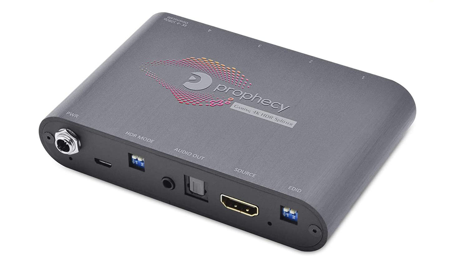
gofanco Prophecy 1x4 HDMI Splitter
The HDMI splitter than I recommend is the gofanco Prophecy 1x4 Gaming HDMI Splitter with HDR to SDR. At the time that I’m writing this article the splitter retails for $99.99 making it one of the most expensive components on the required parts list. The main reason that this splitter costs so much is that it supports HDMI 2.0a and allows simultaneous 4K HDR and 1080p outputs, which is great for an Ambilight setup. Another major benefit is that it also has the capability of tone-mapping HDR to SDR video on the 1080p output. Without the tone-mapping feature we would be sending a washed out (grayish) video image to the Raspberry Pi and the LEDs wouldn’t not match the colors displayed on the screen.
The only drawback I have found with this splitter is that it doesn’t support HDMI CEC. So if you’re like me and like to control your TV using your streamer remote or vice-versa or have your TV automatically your connected devices on/off this splitter will break that functionality.
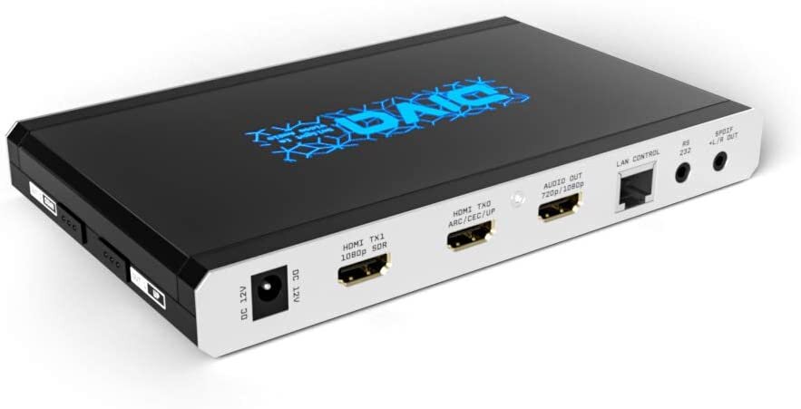
HDFury Diva 4K HDR Splitter
If the lack of HDMI-CEC is a deal-breaker for you then the alternative would be to go with a high-end HDMI splitter like the HDFury Diva 4K HDR Splitter. This is a very sophisticated HDMI splitter that gives you all sorts of options. It might be overkill but the important thing is that it not only supports HDMI-CEC on all HDMI outputs but it also supports advanced tone-mapping on the second HDMI output (1080p) which allows you to customize the tone-mapping even further. The downside is that all of these features come at the steep price of $450. This might cost more than some people’s TV so I doubt most people will want to dish out that much for a splitter. That being said, it is hands down the best option if your money grows on trees.
Wiring The HDMI Splitter
Using The HDMI To USB Capture Device with Loop Out
If you’re using the USB capture device with loop out and you don’t plan on using a separate HDMI splitter then connect everything to the capture device:
Connect the capture device to the Raspberry Pi via USB. (use the USB 3.0 port if you have a Pi 4)
Connect your media player to the HDMI Input.
Connect your TV/Projector to the HDMI Output.
Using the gofanco 1x4 HDMI Splitter
Plug the included power adapter into an available wall outlet.
Connect your media player to “Source”.
Connect your TV to HDMI Output #1.
Connect the HDMI to USB capture device to HDMI Output #4
Set the #4 dipswitch in the down position to force the splitter to downscale the output to 1080p.
Using the HDFury Diva HDMI Splitter
Plug the included power adapter into an available wall outlet.
Connect your media player to “HDMI 0”.
Connect the HDMI to USB capture device to “HDMI TX1 1080p SDR”.
Connect the Diva into your network using an Ethernet cable to access advanced settings using a web browser.
Use your web browser to navigate to the IP address of the Diva.
Navigate to the “Tools” tab at the top of the page.
Under the “HDR to SDR Conversion” section select Profile 1. You can try the other profiles to see which results in colors that match the content on your screen.
Configuring Hyperion
Now that we have your HDMI video capture set up and we can access the Hyperion Web Interface and configuring it. Don’t worry about mounting the LEDs to your screen just yet if you haven’t already since it’s best to test them out and make sure they work properly before you go through the trouble of installing them.
Open a web browser and go to the Hyperion portal that you launched earlier (http://ipaddress:8090)
Click the wrench icon in the upper right corner of the screen and change the settings level to “Advanced”.
Click “Configuration>General” in the navigation menu on the left side of the screen.
(Optional) Click “Rename” to rename the existing “First LED Hardware Instance”. You can name this whatever you want. Some helpful names might be something like RaspberryPi, Ambilight, or PiOutput. Renaming the instance is helpful if you plan on integrating Hyperion into your smart home or if you plan on adding other instances. It’s completely up to you.
Hyperion: LED Hardware
Again, we would have normally mounted the LEDs to the TV before configuring these settings but I recommend testing the LEDs out before mounting them to the TV so we will use estimated numbers then come back and enter the exact numbers later.
Click “Configuration > LED Hardware” from the navigation menu on the left. This is where you configure the communication between the Pi and the LED strip.
The only setting you should have to change on this page is Maximum LED count. If you already mounted your LEDs to the TV then you can enter the total number of LEDs you used. Otherwise just use the total number of LEDs that are on the strip(s) and we will revisit these settings later.
Select the following settings:
Controller Type = ws281x
RGB Byte Order = GRB (This is the setting for the WS2812B or WS1815)
Maximum LED Count = 300 (We will enter the exact number later)
GPIO number = 18
DMA channel = 5
PWM channel = 0
Invert signal = unchecked
Use RGBW protocol = unchecked
White LED algorithm = Subtract minimum
Click “Save Settings
Hyperion: LED Layout
Open the “LED Layout” tab under LED Hardware.
In this screen we need to tell Hyperion exactly how many LEDs are installed on the left, right, top, and bottom of the screen. Again, if you haven’t mounted the LEDs to your screen will use some rough estimates. If you have a strip of 300 LEDs then you can use the following settings temporarily:
Top: 96
Bottom: 96
Left: 54
Right: 54
Gap length: 0
Input position: 0
Reverse direction: unchecked
If you scroll down to the Led Layout Preview section you will see the total number of LEDs, Maximum power consumption, and a preview of how the LEDs will be positioned around your screen. The Max. power consumption information is helpful if you’re not sure what size power supply you should be using. We will revisit this section later.
Hyperion: Capturing Hardware
Open the “Configuration>Capturing Hardware” tab on the left side of the window.
The “Enable platform capture” setting allows you to capture video from the Raspberry Pi itself if we were using the Pi as a video player. We will not be using this setting in this tutorial so this setting should be unchecked.
The “Enable USB capture” setting allows the Pi to capture video from an external USB device. We will be using the HDMI to USB capture device so we need to enable this setting.
Uncheck the box next to “Enable platform capture”.
Check the box next to “Enable USB capture”
Scroll down to the “USB Capture” section and use the following settings:
Device: UVC Camera (xxxx:xxxx) USB Vid (see troubleshooting section below)
Input: Automatic
Video standard: NTSC
Device Resolution: 720x480
Frames per second: 30
Size decimation: 4
Crop left: 0
Crop right: 0
Crop top: 0
Crop bottom: 0
CEC detection: checked
Signal detection: unchecked
**Note: Why do I recommend these specific settings? Using a lower ”Device Resolution” requires less processing power from the Raspberry Pi which leads to lower latency and faster LED response. The “Size Decimation” setting also affects the resolution. Raising the size decimation number lowers the resolution further which leads to even less latency. It’s best to raise this number as high as you can without negatively affecting the accuracy of the LEDs around the screen.
Click “Save Settings”.
**Troubleshooting: The name of your USB Capture device may vary slightly from the name I have listed above. If you don’t see a USB capture device listed in the “Device” dropdown menu try scrolling back to the top of the page and uncheck the “Enable USB Capture box. Click Save settings. Re-check the “Enable USB Capture” box and click Save settings again. Also try unplugging the USB capture from the Pi and plug it back in. If your device still isn’t listed then you may need to restart your Raspberry Pi.
Wiring the LED Strip
Calculating Power Requirements For Your LED Strip
Each LED in the LED strip uses anywhere from 20-60ma. I recommend using LED strips with 60 LEDs per meter so I’m going to assume that’s what you’re using. It’s a good idea to assume maximum brightness when calculating amperage even if you don’t plan to keep them at maximum brightness.
Although I recommend using a separate USB power adapter for the Raspberry Pi, you can power it using the power supply if you’re using the WS2812B strips since they use a 5 volt power supply. If you plan on doing this then you should factor in an additional 3A for the Raspberry Pi.
You can calculate the required power supply amperage for you LEDs using the simple calculation below:
0.06 x NumberOfLeds = maximum amperage
(Ex. 0.06 x 300 = 18A)
If you plan on using the WS2815 (12v) LEDs then you will use the same calculation above to calculate your amperage. Just keep in mind that 12v power supplies will require more wattage than a 5v power supply so 5v is more power efficient.
Most LED strips come in lengths of 3.2ft or 16.4ft. If you purchase a 16.4ft LED strip with 60 LEDs peter meter then the strip will have 300 LED/Pixels which uses a maximum amperage 18A as shown in the example calculation above. If you need a longer strip you can easily add additional strips using the built-in connectors. You can always use a power supply with less amperage but just keep in mind that the LEDs may not reach their full brightness which is usually fine.
Most 5V “wall wart” power supplies (the black power bricks you’re used to seeing) don’t usually come any bigger than 15A so if you need more than 15A then you’ll likely end up with a metal power supply that has exposed electrical terminals. Since this will likely have exposed AC voltage contacts I highly recommend putting this type of power supply inside of a plastic project box. If you don’t feel comfortable with this then you can either use multiple power brick power supplies and tie the positive wires together or use a lower amperage power supply. I use a 40A metal power supply to power a strip of 600 LEDs since they can draw up to around 36A. Alternatively, you could use a computer power supply which often provides more than enough power and doesn’t have exposed AC wires but it creates other challenges that won’t be covered in this tutorial.
Powering The LED Strip
Before we mount the LED strip we need to test it. Powering the LED strip will vary depending on the LED strip model and the number of LEDs you have. For most applications I recommend using 16 gauge wire, especially if the power supply is more than 6 feet away from the LED strip. Some LED strips come with a connector that can be used to splice into your power wires and connect directly to the LED strip. This allows you to conveniently connect or disconnect the LED strip if necessary. You can either use this connector or splice your wires directly into the LED strip wires. The wire colors on LED strips vary between brands so the best way to determine wire color is to look at the markings on the LED strip itself and see what wires are connected to the terminals on the strip. In most cases red is positive and negative is usually white or yellow. Again, it’s best to look at the strip to make sure.
The other end the power wires will be wired to your power supply. If you’re using a power brick style power supply (rectangular black box) then you can either wire the positive and negative wires into the included barrel connector adapter or cut the barrel connector off and splice directly into those wires. These wires are usually black and red. Red is positive, black is negative.
If you’re using a metal power supply with exposed terminals then you may need to connect bare AC wires into the AC voltage terminals and connect the LED strip to the DC terminals.
**Disclaimer: You should always hire or consult with an electrician when working with AC voltage as improper handling can lead to serious injury or death. I am not responsible for any injuries or damage that may be caused from this project. If you don’t feel comfortable working with live AC wiring then I would recommend using multiple smaller 5V power bricks or purchase an LED strip with less than 60 LEDs per meter.
The easiest way to connect the AC terminals to an AC outlet is to use an extension cord and cut off the female end or purchase a 3-wire appliance power cord that already has exposed wires on this end. Most of these cords have white, black, and green wires. Black is hot/positive, white is neutral, and green is ground. DO NOT PLUG THE AC CABLE INTO AN AC OUTLET UNTIL ALL WIRES HAVE BEEN CONNECTED TO THE POWER SUPPLY. Connect the bare AC wires to the respective AC voltage terminals on the power supply.
To connect your 5V wires to the power supply look for a “V+” or “5V+” symbol. Connect the red wire to this terminal and connect the ground wire (usually black or white) to the low voltage ground terminal.
Understanding Voltage Drop
Voltage Drop Example. The strip on right right should be white like the strip on the left. (Photo credit: DerunLedLights)
It’s important to note that long LED strips (over 3 feet) often suffer from voltage drop. This is common with 5v LED strips such as the WS1812B. Voltage drop causes variations in colors at the far end of the strip. This is more noticeable with certain colors and is especially noticeable when trying to produce white. There are two ways to combat this issue.
The first option to address voltage drop is to power the LED strip at multiple locations along the strip (at least every 5 meters). This may seem strange but it does indeed work. Most LED strips have additional power wires at the beginning and end of the strip for this specific reason. If you have a strip of LEDs longer than 7 meters then I recommend powering the beginning, middle, and end of the strip. All of the power connections can connect to a single power supply or they can be connected to multiple power supplies. This ensures that there is consistent voltage along the entire strip.
5V LED Voltage Drop Example (Photo credit: Jujup from Arduino forums)
Another way to address voltage drop is to use a 12v LED strip such as the WS2815. The problem with the WS2812B is that it requires 5v power which is susceptible to voltage drop. The WS2815 is a 12v version of the WS2812B. Higher voltage means that the strip is much less susceptible to voltage drop so the colors are far more consistent on longer runs. If you have a run longer than 5 meters then I still recommend powering the beginning and end of the strip if possible but powering the middle of the strip isn’t usually required unless you have a very long run. The downside to using a 12 volt strip is that you cannot power the Raspberry Pi using the 12 volt power supply without using a step-down voltage regulator since the Pi requires a 5v connection. Connecting the Raspberry Pi directly to a 12 volt power supply will destroy the Pi. If you plan on using a 12 volt strip such as the WS2815 or WS2811 then it’s best to use a separate 3 amp USB power adapter with power the Pi.
Using A Capacitor (Optional)
Although I’ve used WS2812B and WS2815 strips without one, Adafruit recommends using a 1000 µF capacitor to buffer sudden changes in current. It’s important to note that you should always ensure that the capacitor’s voltage is higher than the power supply. The capacitor’s voltage can be significantly higher than the power supply but should never be lower.
5v minimum for WS2812B (Ex. 6.3v)
12v minimum for WS2815 (Ex. 20v)
Most 1000uf capacitors are electrolytic so they are polarized. It’s important that you take note of the markings on the capacitor to determine which lead is the negative side and connect that side to the negative wire. You don’t want to find out what happens if you get this wrong.
Measure the distance between your Raspberry Pi and the LED strip and cut 3 wires to the measured length which will be used for power and data for the LED strip. Connect the power wires to your power supply ensuring that you have the correct polarity (+/-). We will connect the data wire in the next section.

Place the optional capacitor as close to the first LED on the strip. Double check your wiring.

Take note of the negative symbol
Connecting The Data Wire
The easiest way to determine the data wire on your LED strip is to look closely at the LED strip and find the markings. You will usually see 5V, DIN, and GND. 5V connects to the positive 5v terminal of your power supply, GND connects to the 5v negative terminal, and DIN connects to GPIO18 on your Raspberry Pi.
The WS2812B has 3 wires. The two wires on the outside are used to power the strip. The wire in the middle is used for data.
The WS2815 has 4 wires. The two wires on the outside are used for power. The two wires in the center are both used for data. These wires can be tied together to a single data connection.
If you plan to install the Raspberry Pi behind your TV/screen (close to the strip) this will cause the least amount of issues.
If you plan on having your Raspberry Pi farther than 5 feet away from the LED strip then you may run into issues with the data signal.
Take note of the tiny arrows on the LED strip. The arrows should be pointing away from the wires. This indicates the beginning of the strip where you should connect the data wire. Connecting the data wire to the wrong end of the strip will result in no response from the LEDs.
Adafruit recommends using a 470ohm resistor (between 300 and 500 ohms is fine) on the data wire and positioning the resistor as close to the LED strip as possible. Some LED strips already have a resistor built in and I’ve found that the WS2812B and WS2815 work just fine without it but there is no harm in adding it anyways.
Splice one end of the data wire to the data pin on the LED strip and splice the other end to a jumper wire and plug the jumper wire into GPIO18 on the Raspberry Pi.
It’s important to ensure that the Raspberry Pi and LED strips share a ground connection as shown in the illustration above. If you don’t connect the ground from the LED power supply to a ground pin on the Raspberry Pi you may experience severe flickering and sporadic behavior from the LEDs.
Using a Logic Level Converter (Optional)
If you need to run your data wire farther than 5 or 6 feet (1 meter) you may need to use a logic level converter. The logic level converter converts the 3.3v signal from the Raspberry Pi to a 5v signal and allows you to send the data over a much longer distance. If you notice strange behavior from the LEDs such as sporadic flashing or flickering every few seconds then this may fix your issue.
Most Logic Level Converters require you to solder headers to the board so if you can’t find one with headers already installed, you may need to solder it yourself.
Some people recommend placing the resistor close to the strip but I had better success keeping the resistor closer to the Raspberry Pi. This resistor will help to keep the data signal stable over a longer distance as well as protect the LED strip.
Let’s Get To Testing!

Before mounting your LED strip to your screen it’s best to test them out to make sure they’re not defective. Once you have powered on and connected everything using the instructions above, you should see the standby effect from Hyperion. (usually “warm blobs”).
If the LEDs are not responding, try restarting your Raspberry Pi. If they don’t light up after a few minutes then see the troubleshooting section at the end of this tutorial.
If you still have the LEDs on the reel it’s best to either unreel them or limit how long you leave them on for testing as they will produce a lot of heat while lit. If you have a very long strip of LEDs it’s important to make sure that all of the LEDs are evenly lit. If one of the LEDs is malfunctioning it will be noticeable when you install them on your screen.
Time To Install The LEDs
Now that you’ve confirmed that the LEDs work it’s time to install them on the back of the screen.


All TVs are different so placement really depends on your TV. If you’re looking at the back of the TV you’re going to install the LEDs counter-clockwise approximately 1 or 2 inches from the edge of the screen. Try not to put the strip too close to the edge of the TV so the LEDs won’t be visible when viewing the TV from a wide angle. Hyperion assumes that your LED strip starts from the upper right corner of the screen but it doesn’t really matter where you start as long as it’s convenient for you to run the power and data wires. You can fix both the direction and the starting position in Hyperion later if you get it mixed up so don’t worry about this.
If your TV prevents you from having LEDs at the bottom center of the panel then it’s okay to leave a gap. If this is the case then make sure you start from the right side then work your way all the way around to the other side.
There are a 3 ways you can go about handling the corners.
A popular option is to bend the strip so that the corner pokes out a little. This works just fine for most setups and ensures that we still get light in the corner and it prevents you from having to cut and solder.
Another option is to buy LED corner connectors. To use these you just cut the LED strip then clamp the 90 degree adapters to each strip. These work okay but if you don’t install them properly they can ruin that part of the strip forcing you to make a new cut and lose one LED.
The last option is to cut and solder if you’re comfortable with it, This consists of cutting the LEDs and soldering short wires to connect the strips in the corners.
Count the number of LEDs on each side of the TV (Top, Bottom, Left, Right) and take note of the numbers as you’ll need to enter them into Hyperion.
Let’s Get It All Connected
Ensure that you have everything connected using the diagram below as a guide.
The main thing you need to pay attention to when connecting everything is ensuring that your LED strip and Raspberry Pi are grounded together if you’re powering the Pi using USB. This is important because you may run into issues with the LEDs flickering or flashing if you don’t have them grounded together. Even though the Raspberry Pi is powered via USB it should still be connected to the ground of the 5v power supply.
The logic level converter, resistor, and capacitor are all optional items. This setup may work just fine without them.
Let’s Finish Setting Up Hyperion
Now that we have our LEDs mounted to the TV we need to input the exact numbers in Hyperion.
Click “Configuration > LED Hardware > LED Controller” from the navigation menu on the left.
The only setting you should have to change on this page is Maximum LED count. Enter the total number of LEDs that you have installed on your screen.
Select the following settings:
Controller Type = ws281x
RGB Byte Order = GRB (This is the setting you want for the WS2812B or WS1815)
Maximum LED Count = Enter the total number of LEDs that you have installed on your screen.
GPIO number = 18
DMA channel = 5
PWM channel = 0
Invert signal = unchecked
Use RGBW protocol = unchecked
White LED algorithm = Subtract minimum
Click “Save Settings
Open the “LED Layout” tab under LED Hardware.
In this screen we need to tell Hyperion exactly how many LEDs are installed on the left, right, top, and bottom of the screen. Count the LEDs on each side of your screen and enter the numbers. The total number of LEDs should be equal to the “Maximum LED Count” setting you entered in the “LED Controller” tab.
Top: Enter the exact number of LEDs at the top.
Bottom: Enter the exact number of LEDs at the bottom.
Left: Enter the exact number of LEDs on the left.
Right: Enter the exact number of LEDs on the right.
Gap length: If you have a gap at the bottom of your screen you will need to estimate the length of the gap. Use the LED Layout Preview on the right and increase the gap length number until the gap matches your setup. If you don’t have a gap then enter 0.
Gap position: This number controls the position of the LED gap if you have one. Increase this number and use the Layout Preview to determine the location of your gap.
Input position: Hyperion assumes that your strip starts in the upper left corner of the back of your screen. You will need to increase this number and use the LED Layout Preview to determine when the small black gap in the preview matches the location of the beginning of your LED strip.
Reverse direction: If you installed your LEDs counter-clockwise on the back of your screen you should leave this box unchecked. If you installed them clockwise then check this box.
Time To Test It Out
Power on your TV/Projector and media player. If everything is connected and configured correctly, the LEDs should respond to the content on your screen. Try playing some of the Ambilight test videos below to see if your settings are accurate:
Ambilight Test Videos
This video is helpful for testing latency:
Enabling Internet API Access In Hyperion
One cool feature of Hyperion is that it supports remote control using external apps and cloud services. The “Hyperion Free” app can be used to set colors and effects manually. In order to do this you need to enable “Internet API Access”.
Click on Configuration>Network Services in the navigation panel on the left.
Check the box next to “Internet API Access” and click Save settings.
Download the “Hyperion Free” app and enter the IP Address of your Raspberry Pi in the “Hyperion server” field.
Hyperion server: ipaddress:19444
(ex. 192.168.0.64:19444)
You should be able to control the colors and effects of your LEDs from the app. Hitting the power button in the upper right corner will revert the LEDs back to your HDMI capture device.
Troubleshooting
LEDs are flickering and flashing randomly colors rapidly and sporadically.
Make sure you have the ground from the power supply connected to the Raspberry Pi. There are multiple ground pins on the Pi. Use a jumper wire to splice into the ground coming from the power supply to the LED strip.
LEDs are flashing every few seconds or minutes.
The data wire running from your Raspberry Pi to your LED strip may be too long. Either shorten the cable or try using a Logic Level Converter to boost the signal.
Colors appear to be reversed. Example: Green shows up as red, blue shows up as green, etc.
Click “Configuration > LED Hardware” from the navigation menu. Try changing the RGB Byte Order setting. The WS2812B and WS2815 usually requires “GRB”. Try each setting until the colors are correct.
LEDs are black or not responding to video.
Click the small icon in the upper right corner of the Hyperion window that looks like a TV. This should bring up the LED Visualization screen. If the “Live Video” button is red, click the button and it should turn green. When the “Live Video” button is green you should see the live video feed in the center of the screen. This is a live representation of what you should be seeing in real life. If your media player is playing video but this box does not show any video then there is an issue with the HDMI to USB grabber or the HDMI splitter. You can rule out the HDMI splitter by connecting a computer monitor or another TV to the HDMI splitter to see if it shows any video.
LEDs are not lining up properly with screen.
Open the “LED Layout” tab under LED Hardware. Check your LED count and adjust the numbers you have in the top, bottom, left, and right positions as well as the input position.
There is a significant delay between the video and the LEDs response.
Click Configuration > Capturing Hardware. Check the settings in the USB Capture section. Try lowering the Device Resolution setting. Also try increasing the Size Decimation number
USB Capture device does not show up in the Device setting under the USB Capture section.
Click Configuration > Capturing Hardware. Ensure that the “Enable USB Capture” box is checked. If the box is checked, uncheck the box, click “Save Settings”. Check the box and click “Save settings” again. If that doesn’t work try plugging the USB capture device into a different USB port. Also try rebooting your Raspberry Pi.